The chiller is a refrigeration unit consisting of a closed refrigerant circuit (including compressor / s, condenser, thermostatic valve, evaporator, filter drier, connecting pipes and a set of control and control elements) and a water circuit (including ball valves, evaporator, storage tank and a water pump) connected to pipelines that provide transportation of water from consumers and back. Evaporator is a common element for both circuits. Just passing the evaporator, the water cools down (while the compressor is running).
Boiling temperature
The boiling point of a liquid depends on the ambient pressure. The lower this pressure, the lower the boiling point. For example, it is well known that water boils at a temperature of 100C. But this only happens at normal atmospheric pressure (760 mmHg). With increasing pressure, the boiling temperature will increase, and with its decrease (for example, high in the mountains), the water will boil at a temperature much lower than 100C. On average, when the pressure changes by 27 mm Hg. Art. boiling temperature will change by 1C.
Different liquids boil at different temperatures even at the same external pressure. For example, liquid nitrogen boils at a temperature near -77 ° C, and R-22 freon, which is used in refrigeration technology, boils at a temperature of -40.8 ° C (at normal atmospheric pressure).
Heat of vaporization
When a liquid evaporates, heat is absorbed from the environment. When steam condenses, heat, on the contrary, is released. The heat of vaporization of liquids is very high. For example, the energy needed to evaporate 1 g of water at a temperature of 100C (539 calories / g) is much more than the energy needed to heat this water from 0Сo to 100C (100 calories / g)! If liquid freon is placed in an open vessel (with atmospheric pressure and room temperature), it will boil immediately, absorbing a large amount of heat from the environment. This phenomenon is used in the refrigeration machine. Only in it does freon turn into steam in a special compartment - the evaporator. Evaporator tubes are blown by a stream of air. Boiling freon absorbs heat from this air stream, cooling it. But in a refrigeration machine, it is impossible to only evaporate freon, absorbing heat. After all, then a large number of vapors will form in it and it will be necessary to supply more and more liquid freon constantly. Therefore, in the refrigeration machine, the reverse condensation process is also carried out - the conversion from steam to liquid. Condensation of any liquid generates heat, which then enters the environment. The condensation temperature, like the boiling point, depends on the external pressure. At elevated pressure, condensation can occur at very high temperatures. For example, R-22 freon begins to condense at + 55 ° C if it is under a pressure of 23 atmospheres (about 17.5 thousand mmHg).
Refrigeration machine
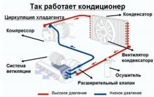
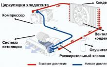
In the refrigeration machine, freon condenses in a special compartment - a condenser. The heat released during condensation is removed by the flow of coolant or air. Since the refrigeration machine must operate continuously, liquid freon must constantly flow into the evaporator, and its vapor into the condenser. This process is cyclic, a limited amount of freon circulates through the refrigeration machine, evaporating and condensing.
One of the main components of the chiller is a condenser, which serves to transfer thermal energy from the refrigerant to the environment. Most often, heat is transferred to water or air. The heat generated in the condenser is approximately 30% higher than the refrigerating capacity of the chiller. For example, if the cooling capacity of a machine is 20 kW, then the condenser generates 25-27 kW of heat.
The compression cooling cycle consists of four main elements:
1. compressor
2. evaporator
3. capacitor
4. flow regulator.
These main elements are connected by pipelines in closed systemwhere refrigerant circulates (usually freon). The refrigerant is circulated in the circuit by the compressor of the chiller.
Compression Cooling Cycle
At the outlet of the evaporator, the refrigerant is steam at low temperature and low pressure. Then the compressor absorbs the refrigerant, the pressure rises to about 20 atm., And the temperature reaches 70 - 90C. After that, hot refrigerant vapor enters the condenser, where it is cooled and condensed. For cooling, water or air is used. At the outlet of the condenser, the refrigerant is a liquid under high pressure. Inside the condenser, the vapor must completely transition to a liquid state. For this, the temperature of the liquid leaving the condenser is several degrees (usually 4-6C) lower than the condensation temperature at a given pressure. Then the refrigerant (having at this moment a liquid state of aggregation at high pressure and temperature) enters the flow regulator. Here the pressure drops sharply, and partial evaporation occurs.
A mixture of vapor and liquid enters the inlet of the evaporator. In the evaporator, the liquid must completely transition to the vapor state. Therefore, the vapor temperature at the outlet of the evaporator is slightly higher than the boiling point at a given pressure (usually 5-8 ° C). This is necessary so that even small droplets of liquid refrigerant do not get into the compressor, otherwise the compressor may be damaged. Superheated steam formed in the evaporator leaves it, and the cycle resumes first.
So, a limited amount of refrigerant is constantly circulating in the refrigeration machine, changing the state of aggregation with periodically changing temperature and pressure.
Each cycle has two defined pressure levels. On the high pressure side, refrigerant condensates and a condenser is located. On the low pressure side is an evaporator, and the liquid refrigerant is converted to vapor. The boundary between the high and low pressure areas passes at two points - at the outlet of the compressor (discharge valve) and at the outlet of the flow regulator.
Refrigerant enthalpy
The cooling cycle taking place in the chiller is conveniently depicted graphically. The diagram shows the ratio of pressure and heat content (enthalpy) of the refrigerant. Enthalpy is a state function whose increment in a process with constant pressure is equal to the heat received by the system.
- The left branch of the curve corresponds to saturated fluid
- The right side corresponds to a saturated pair.
- At the critical point, the branches of the curve are connected, and the substance can be in both liquid and gaseous states.
- Inside the curve is a zone corresponding to a mixture of vapor and liquid.
- To the left of the curve (in the region of lower enthalpy) is a supercooled liquid.
- To the right of the curve (in the region of greater enthalpy) is superheated steam.
Theoretical cooling cycle
In compressor
Cold saturated refrigerant vapor enters the compressor of the chiller (point C1). During compression, its pressure and temperature increase (point D). Enthalpy also increases by an amount equal to the projection of the C1-D line. In the diagram, this is a segment НС1-НD.
Condensation
At the end of the refrigerant compression cycle, hot steam enters the condenser. Here, at constant temperature and pressure, condensation occurs and the hot steam turns into a hot liquid. Although the temperature is almost constant, the enthalpy decreases during the phase transition, and the heat released is removed from the condenser. This process is displayed on the diagram in the form of a segment parallel to the horizontal axis (pressure is constant).
The process in the condenser of the chiller takes place in three stages: removal of overheating (D-E), condensation (E-A) and liquid supercooling (A-A1). The plot of the diagram D-A1 corresponds to the change in the enthalpy of the refrigerant in the condenser and shows how much heat is released during this process.
Removing overheating.
In this process, the vapor temperature drops to saturation temperature. Excessive heat is removed, but the change in the state of aggregation does not occur. At this stage, about 10 to 20% of the heat is removed.Condensation
At this stage, the aggregate state of the refrigerant changes. The temperature remains constant. At this stage, about 60 - 80% of the heat is removed.Liquid subcooling
In this process, the liquid refrigerant is cooled, and a supercooled liquid is obtained. The state of aggregation does not change. Subcooling of liquid at this stage improves the performance of the refrigeration machine. At a constant level of energy consumption, lowering the temperature by 1 degree increases the performance of the chiller by 1%.Flow regulator
The supercooled liquid with the parameters of point A2 enters the regulator of the chiller. It is a capillary tube or a thermostatic expansion valve. A sharp decrease in pressure occurs in the regulator. Immediately after the regulator, the refrigerant begins to boil. The parameters of the resulting mixture of steam and liquid correspond to point B.In the evaporator
A mixture of steam and liquid (point B) enters the evaporator of the refrigeration machine, where it absorbs heat from the environment and completely transfers to steam (point C1). This process occurs at a constant temperature, but enthalpy increases. At the outlet of the evaporator, the vaporous refrigerant overheats a little (segment C1-C2) so that the liquid droplets evaporate completely. To do this, it is necessary to increase the area of \u200b\u200bthe heat exchange surface of the evaporator (by 4-6% for each degree of overheating). Usually overheating is 5-8 degrees, and the increase in heat transfer area reaches 20%. In the evaporator of the chiller, the enthalpy of the refrigerant changes by the value of HB-HC2 equal to the projection of the evaporation curve on the horizontal axis.Real cooling cycle
The actual cooling cycle has some differences from the ideal. This is due to pressure losses occurring on the suction and discharge lines of the refrigeration machine, as well as in the compressor valves. Therefore, the display of the real cycle on the diagram of the relationship between pressure and enthalpy is somewhat different.
Due to pressure losses at the inlet to the compressor, suction must take place at a pressure that is lower than the evaporation pressure (segment C1-L). In addition, due to pressure losses at the outlet, the compressor has to compress the refrigerant vapor to a pressure that is higher than the condensation pressure (M-D1). Thus, the compression work is increased. Such compensation for pressure loss in a real chiller reduces cycle efficiency.
In addition to pressure losses in the pipeline, there are other deviations from the ideal cycle. Firstly, the actual compression of the refrigerant in the compressor cannot be strictly adiabatic (without supply and removal of heat). Therefore, the compression work is higher than theoretically calculated. Secondly, the compressor of the chiller has mechanical energy losses, which leads to an increase in the required electric motor power.
The efficiency of the cooling cycle of the chiller
Chart display:C1-L - suction pressure loss
M-D1 - pressure loss at the outlet
HD-HC1 - theoretical change in enthalpy (heat content) during compression
HD1-HC1 - real change in enthalpy (heat content) during compression
C1D - Theoretical Compression
LM - real compression
To select the best of the cooling cycles, it is necessary to evaluate their effectiveness. Typically, the efficiency indicator of a refrigeration machine cycle is the efficiency or coefficient of thermal (thermodynamic) efficiency.
Coefficient of thermal efficiency- this is: the ratio of the change in enthalpy of the refrigerant in the evaporator (HC-HB) to the change in enthalpy during compression (HD-HC).or: ratio of cooling power to electrical power consumed by the compressor of the chiller.
For example, if the coefficient of thermal efficiency of a refrigeration machine is 2, then for each kW of electricity consumed, this machine produces 2 kW of cold.
Capacitor. Principle of operation.
Air Cooled Condensers
 1 copper tube 2 cooling fins |
Air-cooled condensers are the most common. The air-cooled condenser consists of a fan unit with an electric motor and a heat exchanger. Refrigerant flows through the tubes, and a fan blows air through the tubes. Typically, the flow velocity is 1 - 3.5 m / s. Most often, the heat exchanger consists of finned copper tubes with a diameter of 6 - 20 mm with a distance between the ribs of 1-3 mm. Copper is used because it is easy to process, it does not oxidize and has high thermal conductivity. The fins are usually made of aluminum. The choice of tube diameter depends on many factors: pressure loss, ease of processing, etc. The type of fins can be different and significantly affects the thermal and hydraulic parameters of the heat exchanger as a whole. For example, a complex profile of fins with numerous protrusions and grooves creates turbulence (turbulence) of the air washing the heat exchanger. As a result, the efficiency of heat transfer from the refrigerant to the air increases, and the refrigerating capacity of the chiller increases. |
Two types of connection of tubes with ribs are used:
The holes in the ribs where the heat exchanger tubes are directly inserted. This method is simpler, but reduces heat transfer due to leaking contact. In addition, corrosion may appear in a contaminated environment along the contour, further reducing heat transfer performance.
Collars (collars) at the places where the heat exchanger tubes are connected. This method is more expensive and more complicated, but it provides an increase in the heat transfer surface.
Additionally, the heat transfer of the refrigerant is increased by corrugating the inner surface of the tubes of the heat exchanger. This creates turbulence in the flow of refrigerant.
Typically, a condenser has from one to four rows of tubes located in the direction of refrigerant flow. Often the tubes are staggered to increase the efficiency of heat transfer.
The heat transfer rate varies during the movement of the refrigerant through the tubes. Hot refrigerant enters the exchanger from above and moves down.
At the initial stage (5% of the surface), cooling is most intense, since the maximum temperature difference between the refrigerant and the cooling air and the high speed of movement of the refrigerant.
The main section of the heat exchanger is about 85% of the surface. In this area, the refrigerant condenses at a constant temperature.
The remaining 10% of the surface of the heat exchanger serves for additional cooling of the liquid refrigerant.
The condensation temperature of the refrigerant (freon) is 10 to 20 degrees higher than the ambient temperature, and is usually 42-55C. The heated air leaving the heat exchanger is only 3-5 degrees colder than the condensation temperature.
Water Cooled Condensers
There are three types of water-cooled condenser designs:- Shell and tube
- Type "pipe in pipe"
- Lamellar.
Shell and tube capacitors
In the process of heat exchange, not all air supplied to the evaporator is involved, since part of it passes along the periphery past the heat exchanger. The percentage of air that passes by the evaporator and retains its parameters is called the leakage coefficient. It should strive to lower the coefficient of leakage of air.
A pipe-in-pipe condenser is a system of two spiral tubes, one located inside the other. The refrigerant moves through one of the pipes (external or internal), and water moves along the other. The inner tube is made of copper, and the outer one is made of copper or steel. The surface of the tubes may have fins, which increases the efficiency of heat transfer. Liquids move in oncoming flows, with water entering from below and flowing from above, and refrigerant - vice versa. Pipe-to-pipe condensers are used in stand-alone air conditioning units and low-power cooling units. The disadvantage of this type of capacitors is that the design is one-piece, and only chemical cleaning of the tube is possible.Plate Capacitors
Plate capacitors consist of rows of steel plates arranged "herringbone". Inside the heat exchanger, the refrigerant and water move towards each other along independent circulation circuits.
Therefore, they are widely used in refrigerators of small and medium power.
If the water temperature at the inlet to the condenser is 16 degrees, then the condensation temperature is 32-36 degrees. At a water temperature of + 24 ° C, the refrigerant condenses at 38-40 ° C.
The maximum allowable pressure in the operating mode from the side of the refrigerant circuit is 2.45 MPa, and from the side of the water circuit - 1 MPa.
Evaporator
One of the main components of the chiller is an evaporator, which serves to cool the working environment. Either air, or water or liquids containing antifreeze are used as the working medium of the chiller. Various types of evaporators are designed for cooling different types of working media:- Shell and tube
- Lamellar
Shell and tube evaporators
The shell-and-tube evaporator is a steel cylinder, steel lattices are installed at both ends of the cylinder, to which heads with nozzles for connecting to a water cooling system are mounted. Copper tubes through which water flows are pressed into these grids. Tubes are most often made of copper and have a diameter of 20 mm and 25 mm. Outside, they are ribbed to enhance heat transfer.
The refrigerant circulates through the tubes, coming from the bottom of the evaporator and gradually rising up through the tubes. On the outside, the tubes are washed with water, which is cooled during heat exchange with cold refrigerant.
Water in the shell-and-tube evaporator circulates perpendicular to the tubes and has a speed of 0.5 to 3 m / s due to dividing walls located inside the evaporator casing.
Shell-and-tube evaporators are suitable for handling various refrigerants. The power of these evaporators varies from 7 to 200-250 kW.
Plate Evaporators
Plate evaporators consist of rows of steel plates arranged "herringbone". Inside the heat exchanger, the refrigerant and water move towards each other along independent circulation circuits.Benefits:
- very high heat transfer efficiency.
- compactness and light weight.
- more resistant to freezing in case of breakdown than other types of evaporators.
Evaporators for air cooling
Air evaporators are heat exchangers with one or more (4-6) rows of tubes. Refrigerant flows inside the tubes and cooled air flows between the fins of the evaporator (outside the tubes).
Most often, an evaporator for cooling air consists of finned copper tubes with a diameter of 8 - 13 mm (5/16 ", 3/8" and 1/2 ") with a distance between the fins of 1.4 - 1.8 mm. Copper is used because it is easy to process, it is not oxidized and has high thermal conductivity, and finning is usually made of aluminum.
If the capacity of the chiller is large enough, then air evaporators are made with two or more cooling circuits. Each circuit has an independent supply of refrigerant through a distributor connected to it by thin tubes. All circuits are filled with equal amounts of refrigerant. The air flow is evenly distributed over the heat exchanger, excluding icing of individual sections of the evaporator.
In order to achieve the best quality and stability of the evaporator of the chiller, the power should be 3-7 kW for each heat transfer circuit (when using the most common R-22 refrigerant).
The size of the evaporator depends on the volume of cooled air. The air volume is about 195 cubic meters / hour for each kW of cooling capacity of the installation. The total refrigerating capacity of the evaporator is determined by the temperature of refrigerant evaporation (constant, set during the design of the refrigeration machine), and the temperature of the incoming air (depends on the operating conditions).
The velocity of the air entering the evaporator is usually 2–3 m / s. If the speed is higher, then condensate droplets may slip at the outlet of the heat exchanger. In the evaporator, as in other elements of the chiller, pressure losses occur. They depend on the diameter of the evaporator tubes, the configuration of the fins, the air velocity and the amount of condensate on the fins.
Leakage Rate (Bypass)
Benefits of Low Leakage Rate:
- Increases evaporation temperature and chiller performance
- It is possible to reduce the size of the compressor
- You can limit yourself to a smaller surface area of \u200b\u200bthe heat exchanger. Less heat exchanger tubes needed.
Compressor
One of the main elements of any chiller is a compressor.
The compressor absorbs refrigerant vapor having a low temperature and pressure, then compresses it, increasing the temperature (up to 70 - 90С) and pressure (up to 15 - 25 atm.), And then directs the vaporous refrigerant to the condenser.
The main characteristics of the compressor are the degree of compression (compression) and the amount of refrigerant that it can pump. The compression ratio is the ratio of the maximum outlet pressure of the refrigerant vapor to the maximum inlet.
Refrigerators use two types of compressors:
Piston - with reciprocating pistons in the cylinders
Rotary, screw and spiral - with rotational movement of the working parts
1. Piston compressors
2. Rotary rotation compressors
3. SCROLL scroll compressors
4. Screw compressors
Piston compressors
When the piston (3) moves up the compressor cylinder (4), the refrigerant is compressed. The piston is moved by an electric motor through the crankshaft (6) and the connecting rod (5).
Under the influence of steam pressure, the suction and exhaust valves of the compressor of the chiller open and close.
Figure 1 shows the phase of absorption of refrigerant into the compressor. The piston begins to fall down from the upper point, while a vacuum is created in the compressor chamber and the inlet valve (12) opens. Vapor refrigerant of low temperature and low pressure enters the compressor working space.
Figure 2 shows the phase of vapor compression and its exit from the compressor. The piston rises and compresses the steam. At the same time, the compressor outlet valve (1) opens and steam at high pressure exits the compressor.
The main modifications of reciprocating compressors (differ in design, engine type and purpose):
- Hermetic compressors
- Semi-Hermetic Compressors
- Open compressors
Hermetic compressors
Used in chillers of low power (1.5 - 35 kW). The electric motor is located inside the sealed compressor housing. The motor is cooled by the suction refrigerant itself.Semi-Hermetic Compressors
Used in medium-sized chillers (30 - 300 kW). In semi-hermetic compressors, the electric motor and compressor are connected directly and placed in one collapsible container. The advantage of this type of compressor is that in case of damage, the engine can be removed to repair valves, piston and other parts of the compressor. The motor is cooled by the suction refrigerant itself.Open compressors
They have an external electric motor, taken outside the housing, and connected to the compressor directly or through a transmission. The power of many refrigeration units can be continuously regulated with the help of inverters - special devices that change the speed of rotation of the compressor. In semi-hermetic compressors, another way of adjusting power is also possible - bypassing steam from the exit to the entrance or by closing part of the suction valves.The main disadvantages of reciprocating compressors:
Ripples of refrigerant vapor pressure at the outlet, resulting in high noise levels.High starting loads, requiring a large power reserve and leading to compressor wear.
Rotary rotation compressors
The principle of operation of rotary rotation compressors is based on the absorption and compression of gas during rotation of the plates.Their advantage over reciprocating compressors is low pressure pulsations and a decrease in current at startup.
There are two modifications of rotary compressors:
- With stationary plates
- With rotating plates
Fixed Plate Compressor
In a compressor with stationary plates, the refrigerant is compressed by means of an eccentric mounted on the rotor of the engine. When the rotor rotates, the eccentric rolls along the inner surface of the compressor cylinder, and the refrigerant vapor in front of it is compressed and then pushed out through the compressor outlet valve. The plates separate the high and low pressure areas of the refrigerant vapor inside the compressor cylinder.
Compression and suction continues
The compression is completed, the steam finally filled the space inside the compressor cylinder.
Rotary Plate Compressor
Steam fills the available space
Compression of the steam inside the compressor and absorption of a new portion of refrigerant begins
Compression and suction is completed.
A new cycle of suction and compression begins.
SCROLL scroll compressors
Scroll compressors are used in refrigerators of small and medium power.
Such a compressor consists of two steel spirals. They are inserted one into the other and expand from the center to the edge of the compressor cylinder. The inner spiral is fixedly fixed, and the outer one rotates around it.
Spirals have a special profile (involute) that allows them to roll without slipping. The compressor scroll is mounted on an eccentric and rolls along the inner surface of another scroll. In this case, the contact point of the spirals gradually moves from the edge to the center. The refrigerant vapor in front of the touch line is compressed and pushed into the central hole in the compressor cover. Touch points are located on each turn of the internal spiral, so the pairs are compressed more smoothly, in smaller portions than in other types of compressors. As a result, the load on the compressor motor is reduced, especially at the time of compressor start-up.
Refrigerant vapor enters through the inlet in the cylindrical part of the housing, cools the engine, then is compressed between the spirals and exits through the outlet in the upper part of the compressor housing.
Disadvantages of scroll compressors:
- The complexity of manufacturing.
- A very precise fit of the spirals and tightness at their ends is necessary.
Screw compressors are used in chillers of high power (150 - 3500 kW). There are two modifications of this type:
- Single screw
- Double screw
Single screw screw compressor
Single screw models have one or two satellite gears connected to the rotor laterally.
Refrigerant vapor is compressed using rotors rotating in opposite directions. Their rotation provides a central rotor in the form of a screw. Refrigerant vapor enters through the compressor inlet, cools the engine, then enters the outer sector of the rotating gears of the rotors, is compressed and exits through a sliding valve into the outlet.
The compressor screws must fit tightly, therefore lubricating oil is used. Subsequently, the oil is separated from the refrigerant in a special compressor separator.
Double screw compressor
Double screw models are distinguished by the use of two rotors - the main and the drive.
Screw compressors do not have inlet and outlet valves. The refrigerant is constantly drawn in from one side of the compressor, and the discharge from the other side. With this method of vapor compression, the noise level is much lower than that of reciprocating compressors.
Screw compressors allow you to smoothly adjust the power of the chiller by changing the engine speed.
Flow regulator
1. Capillary tube2. Thermostatic expansion valve
Capillary tube
Liquid refrigerant flowing from the condenser to the evaporator must be dosed. This is implemented using a flow regulator.
The simplest version of the regulator is a capillary tube with a diameter of about 1 mm. They are used in air conditioners of split-systems of low power.
Advantages of capillary tubes:
- Low cost
- Simplicity and reliability in operation, both under constant load and in transient conditions.
The flow rate of the refrigerant through the capillary tube depends only on the differential pressure at the ends of the tube. If the compressor discharge pressure and the evaporator load are not constant, then the flow of refrigerant through the capillary tube may become insufficient or, conversely, excessive.
If the heat load on the evaporator decreases, the liquid refrigerant will not completely turn into vapor, and may damage the compressor if it enters it. This is called water hammer.
If, due to a decrease in the ambient temperature, the condensation pressure decreases, the flow of refrigerant will decrease and the condenser will become insufficient. At the same time, the cooling capacity of the installation will decrease, which, of course, is undesirable.
Thermostatic expansion valve
For powerful air conditioning installations use a thermostatic valve (TRV). It regulates the flow of refrigerant from the condenser to the evaporator so that when the operating conditions change, the evaporation pressure and overheating in the evaporator of the chiller remain constant.There are two types of thermostatic valves:
1. With internal equalization - for low and medium power machines2. With external equalization - for high power machines
The flow rate of the refrigerant through the thermostatic valve depends on the position of the valve. This position is determined by the ratio of forces acting on the regulator membrane.
- Evaporation pressure and spring tension force are directed to closing the valve.
- The valve pressure is directed to the valve opening, which is determined by the overheating of the refrigerant in the evaporator.
Similarly, the action of the regulator with increasing outdoor temperature.
Depending on the length and stiffness of the spring closing the valve of the thermostatic valve, the evaporation pressure and overheating can be set to the desired values
Page 2
Negative temperatures in a given range can be provided by a freon unit with an approximate cooling capacity of about 4000 kcal / h at a boiling point, freon - 35 C and a condensation temperature of freon - - 30 C.
The critical pressures of freons are 4–8 times, the heat of vaporization is approximately 13 times, the thermal conductivity and surface tension are 7 times, the heat capacity and kinematic viscosity are 5 times less than that of water. This causes a number of features of the heat transfer processes during boiling and condensation of freons in comparison with water well studied in this sense.
| Changes in the thermal efficiency of water-freon units at the initial parameters of the freon cycle (Rof 15 - 10 Pa. F 120 C depending on the condensation temperature of freon. |
With equal initial and final parameters, water-freo-new plants have thermal efficiency lower than the basic steam-turbine plants. To achieve equal profitability with equal initial parameters of steam, the condensation temperature of freon should be lower than the condensation temperature of steam for K-1200-240 turbines at 16 - 20 C, for K-800-240 turbines at 17 C, for saturated steam turbines at 8 - 12 FROM.
Ambient temperature is one of the main factors affecting the operation of the refrigerator. With increasing air temperature, the cooling conditions of the condenser worsen, which leads to an increase in the condensation pressure of freon and, as a result, to a decrease in the refrigerating capacity of the compressor. At the same time, the influx of external heat into the refrigerator increases, the pressure and boiling temperature of freon in the evaporator increase. All this affects the cooling of the evaporator and the refrigerator. The refrigeration unit operates with a large coefficient of working time, the power consumption of the engine increases, and the energy consumption increases.
The possibility of condensation of freon in the oil separator is increased when there is air in the condenser, which often happens when low-temperature machines operate with vacuum on the suction side. If there is air in the condenser, the partial pressure of freon in the oil separator is higher than in the condenser, therefore, the condensation of freon in the oil separator occurs at a higher temperature and is possible with relatively warm water.
In freon capacitors, red-copper tubes are used, on the outer surface of which spiral ribs are rolled. The need for ribbing of the surface of freon condensers on the refrigerant side is due to the fact that the heat transfer coefficients are much lower during the condensation of freons than cooling water. The use of copper pipes is explained by the cleanliness of the surface, the absence of corrosion, the ease of rolling of the ribs, and the smaller losses of water pressure. But at the same time, the cost of the condenser increases, the corrosion of steel tube sheets at the junction with copper pipes increases, especially when cooled by sea water. To give the tube sheet complete corrosion resistance against sea water, a layer of copper of considerable thickness is applied to the curly steel surface.
In autonomous air conditioners, two-pipe capacitors were used, which are two tubes inserted into each other and bent into a coil. Sometimes the outer tube is replaced with a rubber hose. In this case, the condensation of freon occurs in the inner tube. Inside the spiral coil in such a condenser is a hermetic compressor, which contributes to the compact arrangement of all equipment.
In the case of the use of highly heat-conducting materials, this phenomenon also takes place, but the values \u200b\u200bof thermal resistance and temperature difference in the wall are small, their increase does not significantly affect the total thermal resistance of steam-cooling water. As a result, the factor of localization of heat fluxes does not significantly affect the overall efficiency of brass or copper shallow tubes when water vapor is condensed on them. However, for the case of condensation of freons, where the heat transfer coefficient on the steam side is relatively small (see), stainless shallow-walled pipes will be quite effective, since in this case the fraction of the thermal resistance of the wall in the total thermal resistance is small.
Most freons used as propellants are in a gaseous state under normal conditions (760 mm Hg and 20 C), with the exception of freons 11 and 113, boiling above 20 C. In the production of aerosol packages, freons are used in a liquefied state . At ambient temperature, a slight increase in pressure leads to the condensation of gaseous freons into a liquid.
Condensation of freon in the oil separator is possible not only during operation, but also when the machine is stopped, when the ambient temperature is lower than the condensation temperature before stopping the machine. To prevent liquid freon from entering the crankcase when the compressor is stopped, it is necessary to close the valve on the line for transferring oil from the oil separator to the crankcase. When starting the compressor, this valve should be opened after the oil separator warms up and the liquid freon evaporates from it. To reduce the condensation of freon in the oil separator after stopping the compressor follows. The need to close the valves complicates the automation of the machine. If there is oil heating in the compressor crankcase, getting a small amount of liquid freon into the crankcase is not dangerous, therefore the bypass line from the oil separator to the crankcase may remain open.
This is one of the most important points in the operation of any air conditioner. We suggest you familiarize yourself with the main points that concern the condensation temperature of freon. A large load on the entire design of the air conditioner is located precisely in the condenser, because it is responsible for cooling the air. This function mainly prevents the possibility of overcooling the system.
Condensation of water on the heat exchanger will never begin until the temperature of condensation of freon is reached. This is primarily affected by the pressure pumped by the compressor of the air conditioner itself. In order to understand when the heat transfer process begins, one must pay attention to when the pressure reaches the critical moment in the condenser. As soon as it is achieved, then the freon gas boils (the condensation temperature of freon reaches its level) and the freon is converted to a liquid state.
Function
The main function of the condenser: by changing the pressure, change the temperature of the freon to its condensation temperature. If we are considering the case of the air conditioner in heating mode, then boiling freon is needed. If cooling, then you need the conversion of freon from liquid to gaseous state.
For its evaporation (transition) to a gaseous state, freon absorbs air heat, and thereby cools it. At the same time, your room is drained, as condensate forms on the heat exchanger, which is discharged through drainage tubes in the form of water.
After one cycle of conversion of freon, the process repeats and as soon as the condensation temperature of freon is reached, it again cools the room, and you enjoy the cool.
Latest reviews
Oasis Comfort CL-9
Angelica
27.06.2016
We bought an Oasis last year. The kitchen of 20 m2 has a partition, so we were advised to take a 9-ku. Now for the air conditioner itself: 1. Pros The most important plus is the price. It has the entire standard set of functions and filters (when it’s not too stuffy, I put it in ventilation mode and this is enough). Heating really works (I don’t know how economical it is, I had to turn it on several times during the winter). Plastic is cheap enough but it looks acceptable. 2. Cons I didn’t really like the remote control, although I often don’t use it. Noisy.
... Oasis Comfort CL-7
Irina Bludova
19.05.2016
Operation of the equipment in modes other than optimal (for example, in conditions of elevated ambient temperatures) affects the efficiency and safety of the refrigeration unit.
The article discusses deviations from the optimal operating mode of the installation, describes the conditions for their identification and elimination.
This material is to a greater extent the answer to questions received by the editors, in particular: " How much does the cooling capacity of my installation fall in such a heat, and what should I do?".
The article will be useful to specialists engaged in the operation of industrial refrigeration equipment.
The main indicators of the operation of the refrigeration unit - cooling capacity, energy consumption, specific energy consumption, water consumption - depend on temperature condition work refrigeration unit.
The most common deviations that affect the efficiency and safety of the refrigeration unit are:
increased temperature of condensation of steam in the condenser;
increased or excessively high steam temperature on the discharge side of the compressor.
Low boiling point *.
The operation of the refrigeration unit at a low boiling point, in addition to the consequences indicated above, can cause freezing of the coolant in the evaporator, freezing of refrigerated goods located near cooling devices, an increase in shrinkage of products, and also deterioration in the lubrication of freon compressors.
Boiling point is a self-adjusting parameter. Its value is determined by the heat influx to the evaporator, the cooling capacity of the compressors, the heat transfer rate in the evaporator and the required temperature of the cooled object.
The lowering of the boiling point occurs when, when the heat load is reduced, the performance of the compressors included in the operation is greater than the performance of the cooling devices. In this case, it is necessary to turn off some of the compressors. When operating compressors with adjustable capacity, it is necessary to turn on the automatic cooling capacity control system and monitor the serviceability of its operation.
The lowering of the boiling point caused by the deterioration in the intensity of heat transfer in the evaporator is due to many reasons.
If there is a lack of refrigerant in the system, the evaporator is not filled completely, and part of its heat transfer surface is not used. The main signs of insufficient refrigerant are its low level in the linear receiver (or condenser), as well as the periodic thawing of the control valve with an increase in its degree of opening. In this case, the system must be replenished with refrigerant. An insufficient amount of refrigerant in the evaporation system may result from improper adjustment of its supply. In this case, it is necessary to ensure the required filling of the evaporation system by opening the control valve larger or by adjusting the automation devices accordingly.
The snow coat deposited on the outer surface of the cooling devices, as well as the greasing of their inner surface, significantly impairs heat transfer and leads to a lower boiling point. Periodic thawing of cooling devices allows not only to free them from the snow coat, but also to release the accumulated oil. The cause of a significant deterioration in the heat transfer of air coolers may be a decrease in the speed of circulating air or a complete cessation of its circulation due to overgrowing of the air cooler or air ducts with a snow coat, poor design of the air circulation system, malfunction of fans or their electric motors.
With flooded ammonia evaporators (shell-and-tube, panel evaporators, collector batteries, etc.), the boiling point may decrease if a large amount of oil accumulates in their lower part, which, occupying part of the apparatus, reduces the active heat transfer surface.
In devices for cooling the coolant with insufficient concentration on the evaporator pipes, ice crust freezes, which, being thermal resistance, causes a lowering of the boiling point. Reducing the coolant circulation due to significant clogging of pipelines, filters, failure of pumps, mixers or their electric motors also lowers the boiling point.
Increased condensation temperature **.
The increased condensation temperature leads to a decrease in the cooling capacity of the installation, an increase in power consumption and a decrease in the technical and economic indicators of its operation.
The condensation temperature is a self-adjusting parameter. The value of the condensation temperature at which self-determination takes place depends on the performance of the compressors turned on, the heat transfer properties of the condenser and the average temperature of the cooling medium. Reducing the increased condensation temperature can be carried out by the methods described above. In some cases, to reduce the condensation temperature in a refrigeration unit with air condensers at high air temperatures, it is advisable to spray water.
The increased condensation temperature during reverse water supply may be caused by the unsatisfactory operation of the water cooling device (cooling tower). Measures aimed at improving its performance are reduced to increasing the supply of circulating water and improving its distribution, as well as to increasing the amount of air passing through the cooling tower.
An increase in condensation pressure can be caused by a deterioration in the heat transfer in the capacitors as a result of:
exclusions from active heat transfer of a part of the surface of the condensers due to their overfilling with liquid refrigerant (insufficient capacity of linear receivers, overfilling of the system or low supply to the evaporative system);
the presence of non-condensable impurities in the condenser (air and oil decomposition products);
reduction of the surface of capacitors due to improper repair of leaky pipes (plugging them instead of replacing them with new ones);
deterioration of heat transfer due to contamination of the surface of the pipes with water stone, sedimentation of silt, algae;
deterioration in the distribution of cooling water due to contamination of nozzles and distributors in vertical, irrigation and evaporative condensers.
In automated refrigeration units, increased condensation pressure may be caused by defects in the operation of the water regulators.
Elevated steam temperature after it is compressed in the compressor.
Exceeding the actual temperature of the injected steam compared to its optimal values \u200b\u200bmay result from increased overheating *** of the absorbed steam, excessive lowering of the boiling point, poor cooling and compressor malfunctions, and the presence of non-condensable gases in the system. Increased superheating of steam at the suction depends on the insufficient supply of refrigerant to the system, the large length of the suction pipelines and the poor quality of their thermal insulation.
The most common compressor malfunctions that cause an elevated discharge temperature are:
significant wear of the compressor cylinder, causing a large pass of steam through the piston rings, as well as leaks of the discharge or suction valves;
insufficient supply of water to the cooling jacket of the compressor or deposition of water stone on its walls, impairing heat transfer through the walls of the jacket;
violation of the lubrication of the surface of the cylinder and heating it due to increased friction of the piston rings against its walls.
For compressors with abundant circulation lubricant (screw and rotary), the temperature of the steam after its compression depends not so much on the temperature of the absorbed steam, but on the temperature and the amount of oil injected.
Humid running of the compressor.
Wet running of the compressor occurs when wet steam is compressed. This is one of the most dangerous abnormalities in the operation of refrigeration units.
The temperature of the liquid refrigerant during compression does not increase, therefore, there is a strong cooling of the compressible mixture, as well as the cylinders and the entire group of compressor movements.
The first sign of wet running of the compressor is a sharp decrease in the temperature of the end of compression. Strong compressor cooling can cause water to freeze in the cooling jacket and rupture of the cylinder block. Increasing the viscosity of the oil and reducing the gaps leads to intensive wear of the compressor. Abrupt cooling of the cylinder from temperatures of about 130-150 ° С to -20 ÷ -30 ° С (when a portion of liquid refrigerant enters the preheated compressor) can cause the so-called heat stroke, as a result of which the compressor cavity is destroyed in the presence of cracks in the metal. If the amount of liquid refrigerant exceeds the dead space of the compressor, there is a danger of water hammer. Discharge valves of the reciprocating compressor exhibit significant resistance to the flow of liquid refrigerant, which leads to an excessive increase in pressure in the compressor cylinder and the occurrence of destructive forces on the crank mechanism. The relative dead volume of reciprocating compressors is about 2-4%. The geometric change in the volume of steam screw and rotary compressors is in the range of 2.6-5.0. Therefore, by the time the compressor discharge cavity is connected to the exhaust window, the volume of this cavity is approximately 20-40% of the original. In addition, for screw and rotary compressors, the cross-section of the outlet windows has a larger area than the cross-section of the discharge valves of reciprocating compressors. Therefore, they are less sensitive to wet running.
Signs of compressor wet running:
no overheating of the suction steam;
lowering the temperature of the injected steam;
changing the sound of a running compressor: the loud knock of valves goes dull and knocks appear in the cylinder;
freezing of compressor cylinders and crankcase.
The main causes of wet steam entering the compressor are:
excess supply of liquid refrigerant to the evaporation system;
boiling of liquid in flooded evaporators with a sharp decrease in pressure in them or with a sharp increase in heat load;
steam condensation in the suction pipe during prolonged parking or low air temperature and poor pipe insulation.
The presence of bags in the suction pipelines increases the risk, when liquid refrigerant and oil accumulate in them, a large portion of the liquid can get into the compressor, leading to water hammer.
If a wet run occurs, immediately close the compressor suction valve and stop the flow of liquid refrigerant into the evaporation system. Open the suction valve so that there are no knocks in the compressor. If a significant amount of liquid refrigerant has got into the compressor and the compressor is very cold, then in some cases it is advisable to open the bypass connecting the suction and discharge lines. In this case, steam with a higher temperature will flow into the cylinders than from the suction pipe, and the compressor can be brought into operation faster. It is strictly forbidden to close the discharge valve in this case.
Photo 1. A fragment of a variant of the appearance of a freon industrial refrigeration unit
on a screw compressor "Bitzer" (Germany): (cooling capacity Q 0 \u003d 229 kW at a boiling point t 0 \u003d +5 ° С and a condensation temperature t к \u003d 45 ° С)* Boiling temperature. The boiling point t 0 is determined by a manovacuum meter connected to the compressor suction pipe. With a decrease in boiling point, the cooling capacity of the installation decreases. The power consumed by the compressor, and depending on the boiling point, can either increase or decrease. Under conditions typical for refrigeration units (t 0 ≤ 10 ° С, t к\u003e 25 ° С), the power decreases with decreasing boiling point, and increases in air conditioning units. Power maxima correspond approximately to P k / p 0 \u003d 3.
A change in boiling point of 1 ° C on average leads to a change in compressor cooling capacity by 4-5%, a change in power consumption by 2%, and a change in specific energy consumption by 2-3%.
The temperature head, i.e. the difference between the air temperature in the cooled object and the boiling point or coolant, is taken in the range of 7-10 ° C. However, in some cases both pressures of 5 ° C (fruit chambers) and 12–20 ° C (ship and domestic installations) are economically justified. For evaporators in which the liquids are cooled, the difference between the average temperature of the liquid to be cooled and the boiling point is taken in the range of 4-6 ° C. The most feasible from an economic point of view is the temperature head for ammonia evaporators 3-4 ° C, for freon 4-5 ° C.
** Condensation temperature. The condensation temperature tk is determined by the temperature scale of the pressure gauge that measures the pressure in the condenser.
An increase in condensation temperature by 1 ° C leads to a decrease in cooling capacity by 1-2%, an increase in power by 1-1.5% and an increase in specific energy consumption by 2-2.5%.
The difference between the condensation temperature and the average water temperature is taken in the range of 4-6 ° C, which corresponds to a condensation temperature of 2-4 ° C, higher than the temperature of the water leaving the condenser. There is a tendency to decrease the temperature difference; in ammonia shell and tube condensers, this difference should be taken equal to from 2 to 3 ° C.
Air heating in air condensers is taken equal to 5-6 ° C, and the temperature difference in the range from 6 to 9 ° C. A lower value of this difference corresponds to a higher cost of electricity, and vice versa.
*** In freon refrigeration units equipped with heat exchangers, steam overheating on the suction side is in the range from 10 to 45 ° C. For low-temperature refrigeration units equipped with several heat exchangers, this overheating can be significantly higher. Overheating of the refrigerant vapor in the evaporator is in most cases undesirable, however, in evaporators with expansion valves (in small chillers), the minimum overheating required for expansion valves (3-4 ° C) is set.
Literature
1. Operation of refrigerators. Bykov A.V. Publishing House "Food Industry", 1977
low boiling point of the refrigerant in the evaporation system;
About the "floating" condensation pressure.
When designing a steam compressor installation, the issue of regulation is important condensing pressure. To increase the energy efficiency of refrigeration systems, step-by-step regulation by pressure switches is replaced by smooth regulation using frequency converters (IF). This is possible for condensation temperatures above 20 0 C (all calculations are for R404A), since this temperature is the minimum allowable for most compressors. But long-term work at the application boundary is unacceptable, therefore, in the calculations we will use the value 25 0 С.
The need to maintain a minimum condensing pressure at low ambient temperatures (to overcome the hydraulic resistance of the system) leads to the mandatory use in the natural environment of Russia "winter regulation kit" condensing pressuree.g. KVR + NRD or ICS Danfoss, together with the inverter.
There are two methods for continuously controlling the condensation pressure using an inverter:
- With a fixed set point (one sensor is used on the high pressure line);
- With a floating set point (one sensor on the high pressure line, the second measures the ambient temperature).
The main difference between these methods is that in the first case, the set value of the condensation temperature is monitored, and in the second, the temperature difference.
Regulation with a fixed setpoint, usually adjusted to the calculated value of the condensation temperature (for example, 45 0 C), is usually used to reduce the energy consumption of condenser fans. But at the same time, such a setting of the condensation temperature leads to an increase in the energy consumption of the compressor due to an increase in the difference in discharge and suction pressure. At the same time, increasing the energy consumption of the compressor, as a rule, is more than reducing the energy consumption of the fans.
The floating setpoint solves this problem. condensing pressurein which the inverter seeks to maintain a given difference between the readings of the ambient temperature sensors (converted to pressure) and the condensation pressure.
To compare the effectiveness of the two described methods, the unit was calculated on the basis of the VOSK HGX34e / 380-4S compressor using the PackColculationIIv3.06 program. The temperature difference for the floating set point method was adopted based on the recommendations, 15K; for the method with a fixed setpoint, the value of the setpoint for the condensation temperature was taken 25 0 С. Such a minimization of the setpoint allows to reduce the degree of compression in the compressor, but leads to an overspending of the energy consumed by the condenser fans, since most of the time the fans operate at the rated speed. If the setting is exceeded, the condenser fans continue to rotate at the rated frequency.
The calculation results are summarized in the table, from which it follows that a system with a floating set point for condensing pressure consumes 141 kWh (0.5% of the total energy saving) more under specified conditions than a system with a fixed minimum set point. Accordingly, from the point of view of energy efficiency, in this case it is advisable to apply precisely the control method with a fixed minimum setting (the value of the setting should be the minimum possible). This conclusion is explainable. We will explain this conclusion: at the minimum setting, the difference between the condensation temperature and the air temperature at the inlet to the condenser is determined by the characteristics of the capacitor, which is selected with a safety factor. With a floating setpoint value, the same difference is set manually, based on recommendations, without taking into account the real characteristics of the selected capacitor, which leads to an increase in the condensation pressure, a greater degree of compression in the compressor and, ultimately, to the energy consumption of the system as a whole.
Reducing the condensation temperature setpoint on the frequency converter from 45 to 25 0 C (or lower, if possible) can achieve significant energy savings that exceed the savings from switching to a floating condensing pressure setpoint. When properly designed with an inverter system, the use of a floating setpoint condensing pressure impractical.


The best material for car trim
Principles of hardening the body
Do-it-yourself compressor - with minimal scrap costs
Which is better: do-it-yourself or factory-made compressor for painting a car
Causes of fuel pump malfunctions