The spraying process is most simply defined by the term “mechanical coating agent”. “Mechanical”, because with an automatic or manual tool (ie paint sprayers) they provide a controlled process of transferring the paintwork material to the surface of the painted product. In this article, we will consider the processes that are required to supply compressed air in painting with spray methods of conventional paint and the tools used for this.
Measures and improvements in the use of compressed air. Cleaning, grinding, polishing: replacing devices for electric drives, painting: replacing high-pressure pneumatic guns Airless systems with which even durable coatings can be processed. Also: powder coating technology, dust removal, drying: for processes to find out whether costs are justified, drilling, screwing up: using electric drives, bending: using electric sticks, fittings: a hammer with an air cushion for flexible casting, but an electric drive for forge operations, control, adjustment, regulation: there are at least technically equivalent solutions for electric current or hydraulics. Compressed air is useful where it must flexibly respond to shocks and loads, cooling: cooling with compressed air is extremely uneconomical - search for alternative systems, tire maintenance: checking all devices, electric screwdrivers instead of pneumatic ones. For all areas of compressed air.
The minimum amount of equipment required to carry out painting work depends on the specifics of the applied paint material. However, its composition is usually included in one of two groups:
Before determining the type of spray equipment (items 5 and 6), we must examine the air supply system and determine the benefits that can be obtained by choosing the right basic equipment.
Compressed air should only be used in special fields. Only prepare compressed air for the required pressure. For special equipment, the required quality must be prepared using decentralized devices. As a rule, only a small capacity is required; the cost of conditioning compressed air of technical quality for laboratory purposes is very high. Pneumatic equipment consumes a lot of energy in classic operation. Waste heat can be used to heat hot water and air for specific areas, such as paintwork, or to heat halls or to use them in different ways.
Compressed air preparation
When creating systems for the preparation of compressed air, it is necessary to take into account the initial state of atmospheric ambient air, which enters the compressors for compression. Why is this so important? The diagrams below show some data on the state of the surrounding air.
![]()
Immediately you can implement: device verification. Monitoring the distribution of compressed air in the idle mode of all devices Checking the load and periods of inactivity For exposure to compressed air: Auxiliary batteries at the point of consumption to avoid large cross-sections, excessive compressor outlets, disconnecting compressed air during ruptures, replacing obsolete components, carrying out pneumatic pipelines in stone masonry in pipes. Long-term measures and investments.
Perhaps every leader of a manufacturing company believes that compressed air is the most expensive energy. The gas envelope in the country does have air. No need to mine, because it's just around us. However, it should be noted that for industrial use it must be compressed, dried, cleaned, as a rule, also treated with oil and then transported to the place of application.
It is generally accepted that in one cubic meter of ambient air there are about 17.5 million different microparticles, and when such air is compressed in the compressor, for example, up to 8 bar, “flows” through it: 17.5 x 8 \u003d 140 million microparticles in one cubic meter, which can adversely affect the state of various consumers, including and during painting work.
In particular, the first part of the process involves the use of appliances consuming electricity. Many people are convinced of the opposite and wasting air. Therefore, managers of some companies are working intensively to raise awareness of the price of this seemingly small subject. For example, one well-known food producer working in four factories in the Czech Republic solves a quiz in an internal magazine. Each employee has a chance to find out that such a cork leak for a peak comes annually up to about 10,000.
Pressure units
The compressed air system is always formed into a complete circuit system, starting and ending with a certain pressure value of atmospheric air. This concept is usually measured in Atmospheres, which is approximately 1 Bar. In DeVILBISS technical documentation, PSI (pounds per square inch) is often found. Compliance with Russian units: 1 bar ~ 14.7 - 15 PSI.
Abroad, they even think of higher grades. A decrease in system pressure causes the compressor to start. The larger the sink, the more often the compressor works and, consequently, the energy consumption. At the same time, electricity consumed by compressors can make up to 20 percent of the total cost of production.
The classic step is to conduct an audit, through which leaks from the system are identified. Audits are conducted by self-service enterprises or specialized firms. An audit usually involves repairing leaks and replacing damaged parts. This process can create significant savings.
Atmospheric air pressure varies slightly depending on weather conditions characteristic of each area at a particular geographical time. If you look at the weather forecast on television (see the example in the figure), you can see that the curved lines on the map (called Isobar) have a closed configuration with areas of equal atmospheric pressure and are marked with values \u200b\u200bin Millibars (mbar or 1/1000 bar).
Undoubtedly, a significant part of the process where leakage is, of course, a matter. Especially at the point of consumption, when air passes through its energy to a mechanical part, such as an air motor or cylinder. Such air is then controlled, or rather injected into space, usually through a filter. Just then, products must optimize the design of their products for the highest possible performance with the lowest possible consumption. Most manufacturers of pneumatic components work intensively with innovation.
For most of Russia, atmospheric pressure typically varies from 990 to 1040 mbar (see figure). However, because atmospheric pressure is always present around us, and its values \u200b\u200bchange relatively little, this error is usually ignored when calibrating DeVilbiss pressure gauges, and usually they have two scales - for measurements in PSI and in atmospheres (bars).
They turn to their customers for new projects. Despite the fact that almost everything seems to be done, there is also a source of hidden money in this area. This, for example, is the problem of operational bending, which practically means a hole in the pneumatic system with a sharp volume of leakage.
There are two most common types of purges. One of them is a pneumatic weapon with mechanical control, which can be used both for impact and for constant use in the production process. The second is a purge nozzle installed as part of the technology on the machine. For both types, the combination of working pressure and opening is projected into the flow, economically speaking, on direct air consumption. Let's look at how to reduce the cost of bending technology while maintaining the desired step.
However, there are other units of pressure measurement, depending on the nationally accepted standards, therefore we give the following basic ratios for ease of use: 14.7 PSI \u003d 1 bar \u003d 100 kPa \u003d 1 kg / cm2 \u003d 750 mm Hg. ct
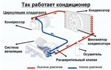
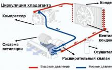
Compressed air circulation
Outside air, passing through the compressor, is usually compressed in a pressure ratio of 8: 1 or 10: 1, depending on the specification and design of the compressor.
The following current and operating values \u200b\u200bare based on actual cases and related measurements. The most commonly used type of purge nozzle is the design called the slang duck leg, a flat design for wider airflow. The option is to use nozzles using the so-called nozzle, which in addition to the main central hole also has openings on the sides that draw air from the atmosphere. This will lead to a significant increase in flow with less air consumption from the manifold.
The energy used to compress air from a source, for example: an electric motor or an internal combustion engine, is transferred to air through the process of compressing gas in an airtight compartment. In an ideal world, such an energy transfer would be 100% efficient, but in fact much less.
This is the first point in the air circulation process under consideration, where work is done and energy is consumed. The amount of energy used will depend not only on the final pressure, but also on the volume of passing air per minute, which the compressor must compress. Compressed air is then supplied to the distribution system (pipelines), where air will flow until the pressure in the system equals the pressure generated by the compressor.
However, with the simultaneous use and price of 1 m³, the compressed air consumption drops to 232 kroons. This gives the user direct financial savings with greater flexibility. If the user is working with jet nozzles, this is another opportunity to use the excess output stream and reduce the number of mounted parts. The key factor is a double increase in flow. If there is a sufficient initial value for the correct operation of the production process, a lower value can be used to control the pressure.
For normal use, the air pressure constantly generated by the compressor is too high, so a special pressure control device called an air regulator is necessary. In this case, the main goal is to reduce the produced air pressure at the compressor outlet (about 14 bar under normal operating conditions) to the pressure suitable for use during painting work (between 0.05 and 7 bar), and maintain this pressure constantly .
Naturally, lower consumption also reduces consumption. Let's do a little recapitulation. The smaller the nozzle, the greater the flow than the original solution, so you can reduce the pressure to 4 bar. In this case, the cost of the control unit or throttle will be incurred. Investments in regulation will return very quickly.
- Consumption drops to 93.6 m³ for 392 kroons.
- Excessive flow rate can be reduced by 2 nozzles.
- For 4 pieces of economical nozzles, 62.4 m³ for 928 kroons will be required.
- The effect of the study will increase to 62% relative to the initial installation.
 This will only be possible if:
a) the compressor maintains the pressure in the line above the required regulated working pressure;
b) the air regulator is capable of processing such a volume of air required to supply the user tool, because the ultimate goal is to transfer compressed air with the required pressure from the regulator, flexible hoses to the tool - spray guns, grinders, etc. The air is consumed by the tool to work, and again passes through the described duty cycle.
However, we must not forget that each case can be specific. To achieve optimal results, it is best to involve a professional company that knows the problem and the appropriate equipment in the design solution. Another important point is the possibility of a trial installation of the nozzle. Testing requires flow measurement. First on the original nozzle, and then on the nozzle using the venturi effect. The measured values \u200b\u200bgive a realistic look at the expected results of the project.
Of course, even the first mentioned explosion variant cannot be omitted by guns. They occur in most enterprises on a much larger scale than technological explosions. They are the most significant source of compressed air waste. Its use is 30 times more loss than usually audible leaks. Unfortunately, the design of conventional guns causes a relatively large drop in pressure of fluid air. This corresponds to the effectiveness and efficiency of such weapons. The average user simply increases the inlet pressure to “hit hard”.
It is important to note that only when air flows in the specified cycle, work can be done, and energy consumed. Therefore, the stored energy will become less and the pressure will decrease as the energy is used.
In the same way, if there are any obstacles to the flow of air, incl. by introducing additional parts into our cycle, then it is necessary to do certain measures to overcome these difficulties. More such obstacles to the movement of air, more energy consumption, more reduced pressure of compressed air in the system.
Unfortunately, he pays a lot more for his work. It is possible to use a gun with an optimized internal design. Pressure loss is usually up to 1%. In combination with the correct nozzle, their explosive pressure, that is, the bending power, will increase by about 25% compared with a conventional design. The price of these types, of course, is higher than that of the so-called "general" ones. Initial investment, however, will return to reduce consumption. Estimated savings are 75%, with very cautious estimates of 20%.
This means that a relatively small change, replacing the gun behind the gun, can significantly affect the consumption of compressed air. As you can see, there are two relatively simple solutions with realistic potential for significant savings in the distribution of compressed air. It must also be understood that these solutions are not self-sustaining. It is important to deal with the problem and not be afraid of investing. Money introduced into innovations or improved equipment, such as ultrasonic leak detectors, will playfully return to energy savings.
These obstacles can be varied - metal ducts themselves, flexible hoses, threaded and quick couplings, air filters, air regulators, and of course any tool actually used. In all cases, such restrictions, by definition, impede the flow of air, reducing the size of the passage available for its flow. Let's look at each of these components of the air circulation system separately to find out how to choose the best equipment.
Summary of steps to improve air distribution efficiency. Regular inspections to detect leaks. Removing detected leaks as soon as they determine the employee incentive system in order to detect leaks of regular training on the proper operation of air distribution and prevent them from being accompanied by additional coverage of the whole organization - quiz, message boards, internally published information. Using innovative solutions - blowers - cylinders , blow nozzles, blow guns, etc. technical equipment with appropriate tools for leak detection, flow measurement, installation and necessary repairs. Partnership with a specialized company with services for air distribution. One of the many aspects of the quality and cost of production processes using compressed air is the quality of this medium.
Air compressors
This is a machine that supplies compressed air with the pressure and in the volume necessary to supply consuming equipment. The compressor consumes atmospheric air at its natural value and compresses it to a higher pressure.
Modern compressor designs have a wide variety of types designed to meet the requirements of different users. They can be equipped with an autonomous electric motor or as a separate mobile unit equipped with a gasoline engine, receiver and cooler. Such equipment can be applicable for both light and severe operating conditions, and have power limits from 0.2 to thousands of horsepower (hp). They are also for domestic or industrial use.
Note: We use a parameter such as “Horsepower (hp)” to indicate power in relation to the electric, gasoline or diesel engine that feed the compressor. There is an alternative unit of power - kilowatts (kW). 1hp \u003d 0.75 kW
Compressed air is an expensive form of energy compared to electricity, steam, or hydropower. Therefore, air compressors must have good efficiency. Since the compressor is designed to maintain the required volume of air, its efficiency is called Volume Efficiency. To determine this better, we need to consider some points in the operation of the compressor.
The operation of the compressor is expressed in accordance with two concepts:
1. Volume
This is the amount of air that the compressor emits at the end of the compression phase. The amount of air depends on the configuration and type of compressor design, the size of the air cylinder and the engine speed. For example, if the cylinder of a reciprocating compressor has a size of 0.03 m3, the engine is 500 rpm, the volume of air produced in this case will be 15 m3 / min. In fact, such a volume of air is a theoretical value, which is obtained at 100% compressor efficiency. However, like any other machine, this efficiency is much less than 100% due to losses such as heating, friction, leakage, etc.
2. Free Air Delivery (FAD)
This is the actual volume of air produced (in m3 / min) that the compressor produces. This amount of air suitable for consumption is always less than the design capacity of the compressor. The degree of their ratio is expressed as:
Volumetric Efficiency \u003d FAD to Volume ratio.
For instance. Volume of air produced - 3 m3 / min: FAD - 1.5 m3 / min \u003d Volumetric Efficiency \u003d 50%
You must understand that the best compressor is also the most efficient. Therefore, the best is the one that works with the least amount of air loss, and has an efficiency of 80% or higher. Compressors are equipment manufactured with high accuracy and thoroughness, therefore the experienced advice of a specialist will never hurt when buying.
The main points that you need to pay attention to when choosing a compressor:
1. Pressure generated (in PSI, bars or atmospheres)
2. Volume of air supply (m3 / min or l / min)
It is important to keep in mind that the cost of compressed air received for consumption is not at all equal to the price of the compressor itself, but mainly includes various operating costs (for example, electricity).
Compressors, of course, can be heated or cooled during operation. In fact, the physical compression process itself leads to an increase in the temperature of the compressed air. The compressor, which remains the coolest during operation, has the highest efficiency. Therefore, that compressor, which is never cleaned from dust, dirt or settled paint, has increased insulation from removing excess heat and, naturally, increases the temperature of its working surfaces, and, consequently, low efficiency.
Types of Air Compressors
All compressors used in the paint industry are of volume type, that is, a certain amount of air, placed in a confined space, is compressed to a predetermined pressure value. Depending on the size and type of work performed, there are several different types of compressors.
 Diaphragm compressors
Their use is limited by the consumer market - the so-called "do it yourself". These are usually quite small, portable machines with low performance. Powered by a single-phase 220V network, these rather cheap compressors have a small output power (typically 0.18-0.75 kW), and very low productivity (28-112 l / min). Because of their simple design, they have no more than 60% efficiency.
Piston compressors 
Available in a wide range of sizes and capacities, they are the most popular type of compressors used worldwide. Their robust and fairly simple design has made them extremely popular.
There are stationary and mobile versions, the power varies from 0.4-9 kW. However, more powerful compressors have only industrial design. Piston compressors have higher efficiency - in the range of 65-75%.
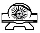 Turbine compressors
These are machines in which in a motionless cylindrical casing, a rotor blade rotates at high speed. Lubricated and non-lubricated designs are available. In such compressors there is practically no ripple phenomenon. It is an ideal compressor for the production of large volumes of air for large industries. They are usually of a stationary type, powered by a 3-phase electric network, and have a power in the range of 2-30 kW. Although such compressors have higher operating costs than piston ones, their low noise and high efficiency (70-80%) give good profitability and popularity.
Screw compressors 
These are machines in which two conjugated rotors of a screw or spiral design, when rotated together, create a difference in air pressure, compressing it to a certain value. Having such good characteristics as low noise, low ripple and high efficiency (95-98%), they are usually regarded as the best, but also the most expensive compressors currently available. They have wide power limits, larger than other types of compressors (3.75-450 kW).
Air Compressor Care
The design of modern compressors gives them very high efficiency and a long service life, provided that they are regularly checked and quickly restored when necessary. While in large industries there is always trained qualified personnel for the maintenance of compressors, smaller industries must necessarily come into contact with the service departments of compressor manufacturers or their dealers on service issues.
Typically, daily work for any compressor user includes:
a) removal of accumulated liquid from receivers and pulsation chambers
b) checking the lubrication levels in the crankcases of engines or cooling systems
c) checking the filters of the intake port and the air outlet fitting for the degree of contamination.
For all work, it is imperative to follow the recommendations of the compressor manufacturer or its supplier.
Dehumidifiers
Like compressors, they are specialized pieces of equipment that require professional selection and maintenance to get the best results. Removing moisture from the air is very important to obtain a quality result when painting. In addition, moisture removal prevents corrosion and destruction of air motor blades in pneumatic grinding tools.
Dehumidifiers will remove moisture to a specific level called the “Dew Point”. This is the lowest temperature to which the air must be cooled in order to begin the release of moisture from it.
Today, there are two main types of dehumidifiers:
Refrigerated Driers
In this type of dehumidifier, the incoming air is cooled to the appearance of the moisture vapor contained in it - typically at low temperatures, only above the freezing point of water. The lower the temperature, the more humidity will be released. The system is very similar to a home refrigerator. This type of drainage is a continuous process, has an automatic drainage system to constantly get rid of the released moisture.
Absorption Dehumidifiers
They are a container that contains a certain amount of a moisture-absorbing reagent, for example, selicogel or activated alumina, which have the ability to dehydrate air or other gas. The flow of compressed air passing through the granules of the reagent is freed from moisture, is supplied to the tools, however, it does not reduce its initial temperature. The disadvantage of this type of dehumidifier is the inability to recycle or restore the reagent as soon as they are fully saturated with moisture. Therefore, it is necessary to carefully monitor the condition of the reagents and replace containers in time.
There are more expensive and larger versions of this type of dehumidifier, which include reagent recycling equipment built into containers. In this case, two working cylinders are used - one to remove moisture, the other simultaneously processes and restores the reagent. This allows you to remove moisture continuously during the working day. The most popular recirculation method is the use of a special heater that drains the reagent itself. Since this method uses an absorption process rather than a precipitation process for drying, the dew point can be between -1 ° C ... -10 ° C.
It should be noted that both types of dehumidifiers considered are designed to remove moisture only. They do not remove substances in the air such as carbon monoxide, carbon dioxide, hydrocarbons, or even particles of dust and dirt. Other measures and other equipment are needed to eliminate these types of contaminants. In addition, removing too much moisture from the air intended for breathing is just as bad. Therefore, the effectiveness of the use of one or another type of dehumidifier should be studied at the stage of packaging equipment for the preparation of compressed air.
Compressed Air Receivers 
This equipment serves to absorb pulsations in the outlet line from the compressor, adjusts the air flow to the consumption lines and serves as a reservoir for compressed air regardless of the operation of the compressor. To select the required receiver capacity, the compressor performance and air consumption requirements must be taken into account. As a rule, to determine the characteristics of the receiver, take the dependence of the volume of the receiver (in liters) on the performance of the compressor (liters per second). It empirically amounts to: Vr (l) \u003d 6 ... 10 PrK (l / s)
Another feature of the receiver is that it releases moisture from the air. Therefore, the receiver must, accordingly, be released daily from accumulated moisture. The receiver must be placed in the coolest place of production. It should be equipped with an auxiliary pressure valve, pressure gauge, inspection holes, drain valve, identification marks. It is also necessary to provide sufficient external access to the receiver for maintenance and inspection.
Compressed air lines
Traditionally, production workshops have been equipped to supply mainly metal pipelines with compressed air, especially over long distances. Long flexible hoses are not recommended for this because of the possibility of their rapid wear or leakage. But today, air pipelines can be made mainly of stainless or galvanized steel, ABS plastic, copper alloys.
The working diameter of the pipelines should never be smaller than the size of the outlet fitting of the compressor or receiver. The largest internal diameters and the shortest possible length of pipelines will guarantee minimal pressure and energy losses. In addition, the bends of the pipeline should be with the largest possible radius to reduce losses. The piping routes from the compressor to the consumers should be as simple and simple as possible, with as few bends, intersections, insets or connections as possible. The table below provides recommendations for choosing air pipelines.
The pneumatic equipment of the subway car consists of six independent pneumatics and highways that combine a set of devices depending on the purpose
1. NP - a set of devices providing the creation of compressed air, its purification from mechanical impurities, oil, moisture and storage, to ensure the operation of all pneumatic devices.
Pressure - 6.3-8.2; volume - 425 liters.
2.TM - provides all types of pneumatic braking and brake release.
Pressure - 5.0-5.2; volume of 29 liters.
3.DM - provides automatic doors
Pressure 3.4-3.6; volume of 8 liters.
4. MU - provides the inclusion of power electrical apparatus
Pressure 5.0-5.2; volume is included in NM
5. Hitchhiking - provides an emergency brake when the stall valve is triggered, turning off the traction motors.
Pressure 5.0-5.2; volume - included in TM
6. SIGNAL, CONTROL, AUXILIARY DEVICES HIGHWAY - provides pressure control in a shopping center, TM, NM, sound signal, wiper operation.
Has no constant pressure.
Purpose and arrangement of junction boxes SK43, SK25.
SK-43 (Power box). It is intended for connection of TP power cables and SC cable (circuit).
Box connecting SK-43B
1 - metal welded box; 2 - a metal cover with a rubber seal; 3 - insulating panel; 4 - clamps for suitable wires; 5,6 - terminal device.
Attaches to the frame on the left:
The insulating panel on which the terminal device is mounted for clamping the cable lugs of the SC;
Metal cover with rubber seal, fastened with 2 wing clips.
SK-25ZH. "Earthen box", on the carriage 2 boxes. Designed for connecting wires and cables of SC, VspTs and TsU, subject to grounding. (show in the diagram)
Metal welded box;
The insulating panel on which the contact strip is mounted for clamping the tips;
Metal cover with rubber seal, secured with 2 wing clips.
Box connecting SK-25ZH.
1 - metal cover 2 - metal welded box 3 - insulation panel
The principle of operation of BP conv. No. 337.004 with full service braking and
Brake release.
For full service braking (PST), it is necessary with the help of a crane operator to lower the pressure in the brake line on the composition in one go with 5 at. up to 3 atm. At the same time, during a decrease in the pressure of compressed air in the TM, the pressure also decreases in the main chamber of the main part of the BP connected with it. Since in the neutral position of the main diaphragm the main and working chambers communicate with each other through the charging valve and the calibrated hole in the upper part of the clamp of the main diaphragm (d \u003d 0.8 mm), the compressed air pressure also begins to fall in the working chambers. But the diameter of the hole calibrated relative to the volume of the working chambers is designed in such a way that the pressure reduction of compressed air in the working chambers occurs only slightly (due to the small diameter of the hole, the air from the working chambers does not have time to flow into the main chambers). Due to the resulting pressure difference in the main and working chambers, the main diaphragm bends upward by the force of compressed air from below, compressing the load spring. When the diaphragm rises up, the charging valve closes by the force of its spring and the communication between the main and working chambers ceases (Fig. 9). Thus, it is obvious that a certain pressure of compressed air (about 4.7-4.8 at) was fixed in the working chambers, which keeps the main diaphragm in the upper position. When lifting up, the main diaphragm acts from below on the rod, with 3 cuffs fixed in its clamp from above. The rod, moving upward, cuts off the additional discharge chamber from the atmosphere, and its middle and lower cuffs inform the CRC with the brake line. In this case, an additional discharge of the TM in the KDR occurs and the main diaphragm bends up even higher until it stops in the housing and the response speed of the VR to the brake increases. In turn, the rod with cuffs acts on the mode rod from below, which also moves upward, together with the large and small mode springs and the mode piston, acts on the mode diaphragm from below, and it bends upward, overcoming the force of its load spring. It should be noted that when lifting up, the operating springs do not compress, and when the pressure of compressed air in the brake chamber increases, they are compressed by the force of the operating diaphragm and enable it to partially bend down. When the operating diaphragm rises, the atmospheric valve closes, separating the brake chamber and the brake cylinders from the atmosphere. When closing, the atmospheric valve acts on its movable seat — the lower end of the hollow tube with the feed valve. The hollow tube under the influence of the diaphragm (atmospheric valve) from the bottom moves upward, overcoming the force of the return spring of the feed valve. The feed valve opens, communicating the pressure line with the brake chamber and brake cylinders through the channels of the shopping center and OTC. The process of filling with air will continue until the pressure of the compressed air in the brake chamber (and consequently in the brake cylinders), combined with the force of the load spring of the operating diaphragm, overcomes the force of the operating springs (through the operating piston) on the operating diaphragm from below. As soon as this happens, the diaphragm will make a partial move down. In this case, the feed valve closes by the force of the return spring. The atmospheric valve will remain closed. There will come a position of a full balance of forces - overlapping, with a fixed, maximum possible pressure in the brake cylinders (2.7-2.9 atm when empty), which depends on the adjustment of the operating springs relative to the area of \u200b\u200bthe operating diaphragm.
Brake release.
For a complete release of the brake, it is necessary to charge the brake line with the help of a crane operator to a working pressure of 5 bar. At the same time, the pressure of compressed air also increases in the main chamber. When the pressure of the compressed air in the main chamber is greater than or equal to the pressure of the compressed air in the working chambers, the main diaphragm with a rod with cuffs will bend down (by the force of compressed air and the load spring from above) and take a neutral position. Deprived of support from below, the operating rod, operating springs and operating piston, also move down. The diaphragm at the same time, by the force of compressed air and the load spring from above, will bend down and, like the main diaphragm, will take a neutral position. The atmospheric valve will open and the brake chamber, and therefore the brake cylinders, will communicate with the atmosphere through the channel of the hollow tube and the atmospheric openings in the upper base cover of the BP.


The best material for car trim
Principles of hardening the body
Do-it-yourself compressor - with minimal scrap costs
Which is better: do-it-yourself or factory-made compressor for painting a car
Causes of fuel pump malfunctions